


Selecting the appropriate diameter for your copper line set installation represents one of the most critical decisions in HVAC system design and implementation. The diameter directly influences system efficiency, refrigerant flow characteristics, and overall performance of air conditioning and heat pump systems. Professional HVAC technicians understand that incorrect sizing can lead to reduced capacity, increased energy consumption, and premature equipment failure. Modern copper line set configurations require precise calculations that account for refrigerant type, system capacity, line length, and environmental factors to ensure optimal performance throughout the system's operational lifespan.
Understanding Copper Line Set Fundamentals
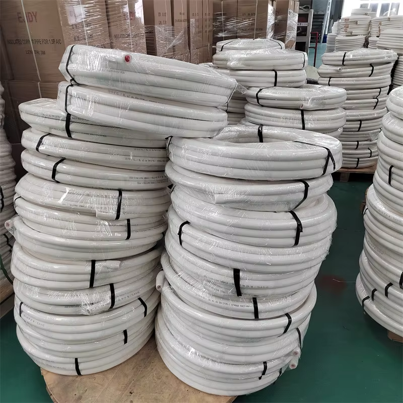
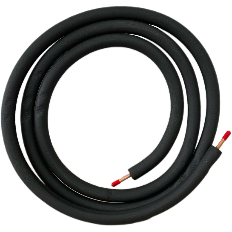
Basic Components and Configuration
A copper line set consists of two primary components: the liquid line and the suction line, each serving distinct functions within the refrigeration cycle. The liquid line carries high-pressure liquid refrigerant from the condensing unit to the evaporator coil, while the suction line returns low-pressure vapor refrigerant back to the compressor. These copper tubes must maintain specific diameter relationships to ensure proper refrigerant velocity and system balance. The insulation surrounding the suction line prevents condensation and maintains refrigerant temperature, while the liquid line typically requires no insulation in most residential applications.
Manufacturing standards for copper line set products specify precise tolerances for wall thickness, diameter consistency, and material purity. Quality copper tubing exhibits excellent thermal conductivity, corrosion resistance, and durability under varying temperature and pressure conditions. Professional-grade line sets undergo rigorous testing to verify leak-tight connections and proper insulation adhesion. The copper material must meet ASTM B280 specifications for seamless copper tube intended for air conditioning and refrigeration field service applications.
System Capacity Relationships
The relationship between system capacity and copper line set diameter follows established engineering principles based on refrigerant flow requirements and pressure drop limitations. Larger capacity systems require proportionally larger line diameters to accommodate increased refrigerant flow rates without exceeding acceptable pressure drop thresholds. Undersized lines create excessive pressure drops that reduce system capacity and increase compressor workload, while oversized lines may cause oil return issues and reduced refrigerant velocity. Proper sizing ensures optimal heat transfer efficiency and maintains manufacturer warranty requirements.
Capacity calculations must consider both sensible and latent heat loads, accounting for peak demand conditions and system operating characteristics. The copper line set diameter selection directly affects the system's ability to maintain design temperatures under varying load conditions. Engineers utilize specialized software and calculation methods to determine optimal line sizing based on specific application requirements, refrigerant properties, and installation constraints.
Technical Sizing Calculations
Refrigerant Flow Dynamics
Refrigerant flow through copper line set installations follows complex thermodynamic principles that govern velocity, pressure drop, and heat transfer characteristics. The liquid line must maintain sufficient subcooling to prevent flash gas formation, while the suction line must provide adequate velocity for oil return without excessive pressure drop. Velocity calculations consider refrigerant density, viscosity, and flow regime transitions that occur under different operating conditions. Professional sizing charts and calculation tools provide guidance for determining appropriate diameters based on system capacity and refrigerant type.
Modern refrigerants exhibit different flow characteristics compared to traditional refrigerants, requiring updated sizing methodologies for copper line set installations. R-410A systems, for example, operate at higher pressures and may require different velocity considerations than R-22 systems. The selection process must account for refrigerant-specific properties including density, enthalpy, and transport characteristics that influence line sizing requirements. Proper analysis ensures optimal performance across the full range of operating conditions.
Pressure Drop Analysis
Pressure drop calculations form the foundation of proper copper line set sizing, as excessive pressure losses directly impact system capacity and efficiency. The liquid line pressure drop affects subcooling margin and can cause refrigerant flashing if inadequately sized. Suction line pressure drop reduces evaporator pressure, decreasing system capacity and potentially causing compressor overheating. Industry standards typically limit liquid line pressure drop to equivalent of 1-2°F subcooling loss, while suction line pressure drop should not exceed 2-3°F evaporator temperature penalty.
Calculation methods incorporate friction factors, equivalent length for fittings, and elevation changes that contribute to total system pressure drop. The copper line set length significantly impacts pressure drop calculations, with longer runs requiring larger diameters to maintain acceptable performance levels. Advanced calculation software considers multiple variables simultaneously to optimize line sizing for specific installation requirements.
Installation Environment Considerations
Temperature and Climate Factors
Environmental temperature conditions significantly influence copper line set performance and sizing requirements. Ambient temperature variations affect refrigerant properties, system operating pressures, and heat transfer characteristics throughout the installation. High ambient temperatures increase condensing pressures and may require larger liquid line diameters to maintain adequate subcooling margins. Cold climate applications must consider refrigerant viscosity changes and potential oil return issues that may necessitate modified sizing approaches.
Insulation effectiveness varies with temperature differentials and environmental exposure conditions. Copper line set installations in extreme climates require enhanced insulation specifications and potential sizing adjustments to compensate for increased heat transfer losses or gains. Humidity levels affect condensation potential on suction lines, influencing insulation requirements and installation practices. Professional installations account for seasonal temperature variations and peak load conditions when determining optimal line sizing.
Routing and Installation Constraints
Physical installation constraints often influence copper line set diameter selection and routing decisions. Available space for line routing, structural penetrations, and accessibility requirements may limit diameter options or necessitate alternative routing strategies. Vertical lift requirements affect refrigerant velocity calculations and may require larger suction line diameters to ensure adequate oil return under all operating conditions. Complex routing with multiple bends and fittings increases equivalent length calculations and pressure drop considerations.
Installation practices must maintain minimum bend radius requirements to prevent line restrictions and ensure proper refrigerant flow. The copper line set routing should minimize pressure drop while providing adequate support and protection from physical damage. Professional installers coordinate line sizing with architectural constraints and building requirements to achieve optimal system performance while meeting code compliance standards.
Performance Optimization Strategies
Efficiency Maximization
Optimizing copper line set diameter selection directly contributes to overall system efficiency and operating cost reduction. Properly sized lines minimize energy losses associated with excessive pressure drops while maintaining adequate refrigerant velocities for effective heat transfer. The balance between line size and system performance requires careful analysis of operating costs versus initial installation expenses. Larger diameter lines reduce operating costs through improved efficiency but increase material and installation costs.
Energy efficiency considerations extend beyond basic sizing calculations to include system control strategies and operating characteristics. Variable capacity systems may require different sizing approaches compared to single-speed units due to varying refrigerant flow rates under different load conditions. The copper line set sizing must accommodate the full range of system operation while maintaining optimal efficiency at typical operating points.
Long-term Reliability
Proper copper line set sizing contributes significantly to long-term system reliability and maintenance requirements. Undersized lines create stress conditions that can lead to premature component failure and increased maintenance needs. Excessive refrigerant velocities may cause erosion or vibration issues, while inadequate velocities can result in oil logging and compressor lubrication problems. The sizing process must balance immediate performance requirements with long-term reliability considerations.
Quality copper line set materials and proper sizing work together to ensure extended service life and minimal maintenance requirements. Professional installations that follow manufacturer specifications and industry best practices typically demonstrate superior reliability compared to improperly sized systems. Regular system monitoring and maintenance help identify potential issues before they result in system failure or significant performance degradation.
Common Sizing Mistakes and Solutions
Oversizing Consequences
Oversizing copper line set installations can create performance problems that are often less obvious than undersizing issues but equally detrimental to system operation. Excessively large suction lines reduce refrigerant velocity below minimum requirements for effective oil return, potentially causing compressor lubrication failure over time. Low velocity conditions may also result in refrigerant stratification and uneven heat transfer characteristics throughout the evaporator coil system.
Large diameter liquid lines can cause refrigerant subcooling variations and potential control issues in systems with electronic expansion valves or capillary tube metering devices. The increased internal volume of oversized copper line set installations requires additional refrigerant charge, increasing system costs and environmental impact. Professional sizing methodologies help avoid oversizing while ensuring adequate capacity for peak load conditions and future system modifications.
Undersizing Problems
Undersized copper line set installations create multiple performance and reliability issues that become apparent during system operation under various load conditions. Excessive pressure drops reduce system capacity and increase energy consumption as the compressor works harder to maintain design conditions. High refrigerant velocities in undersized lines can cause noise, vibration, and erosion problems that affect system reliability and occupant comfort.
Liquid line restrictions may cause refrigerant flashing and erratic expansion valve operation, resulting in poor temperature control and reduced efficiency. Suction line restrictions increase compressor suction temperature and may cause overheating protection to activate during peak load conditions. Proper copper line set sizing prevents these issues while ensuring optimal system performance throughout the operating envelope.
Professional Installation Practices
Quality Control Measures
Professional copper line set installations incorporate comprehensive quality control measures to ensure proper sizing implementation and long-term system reliability. Verification procedures include pressure testing, leak detection, and insulation integrity checks that confirm installation quality. Dimensional verification ensures that delivered line sets match specified diameters and lengths according to engineering calculations and manufacturer recommendations.
Installation documentation should include detailed sizing calculations, material specifications, and testing results that demonstrate compliance with industry standards and local code requirements. Professional contractors maintain detailed records of copper line set specifications and installation procedures to support warranty requirements and future service needs. Quality installations follow manufacturer guidelines for handling, storage, and installation practices that preserve material integrity and system performance.
Code Compliance and Standards
Copper line set installations must comply with applicable mechanical codes, safety standards, and manufacturer specifications to ensure safe and legal operation. Local building codes may specify minimum sizing requirements, installation practices, and inspection procedures that govern line set installations. Professional contractors stay current with code changes and industry standards that affect copper line set sizing and installation requirements.
Industry organizations provide guidelines and standards that establish minimum performance requirements for copper line set installations in various applications. Compliance with these standards ensures compatibility with equipment warranties and provides assurance of proper system performance. Professional installations that meet or exceed applicable standards typically demonstrate superior reliability and performance compared to installations that merely meet minimum requirements.
FAQ
What factors determine the minimum diameter for a copper line set installation
The minimum diameter for a copper line set installation depends primarily on system capacity, refrigerant type, line length, and acceptable pressure drop limits. Engineers calculate minimum diameters based on required refrigerant flow rates and maximum allowable pressure losses that ensure adequate system performance. Industry standards typically limit liquid line pressure drop to equivalent subcooling loss of 1-2°F, while suction line pressure drop should not exceed 2-3°F evaporator temperature penalty.
How does line length affect copper line set diameter selection
Line length directly impacts pressure drop calculations and may require larger diameters for longer runs to maintain acceptable performance levels. Friction losses increase proportionally with line length, while elevation changes add static pressure components that affect overall system pressure drop. Extended copper line set runs may also require consideration of oil return velocity requirements and refrigerant charge adjustments that influence sizing decisions.
Can I use different diameter copper line sets for the same system capacity
Different diameter copper line set configurations may be suitable for the same system capacity depending on installation constraints, line length, and performance requirements. Longer runs typically require larger diameters to compensate for increased pressure drop, while shorter runs may allow smaller diameters while maintaining acceptable performance. However, any diameter selection must be verified through proper engineering calculations to ensure adequate refrigerant flow and pressure drop characteristics.
What are the consequences of using incorrect copper line set diameters
Incorrect copper line set diameters can cause significant performance problems including reduced system capacity, increased energy consumption, and potential equipment damage. Undersized lines create excessive pressure drops that force the compressor to work harder and may cause overheating protection activation. Oversized lines can result in inadequate oil return velocities, refrigerant control issues, and increased system costs due to higher refrigerant charge requirements.